Thursday 12 December 2019

Rational Rhapsody Tip #71 - Use case diagrams in Rational Rhapsody (Simple)

This is the 3rd in a series of videos I'm created showing Rational Rhapsody's implementation of diagrams in the Unified and Systems Modeling Languages (UML/SysML). This video, which includes narration, covers the use case diagram. Use case diagrams are a core notation in both UML and SysML. However, I often find them one of the notations that is both simple but easy to get wrong, particularly when engineers forget that the use case isn't actually described in the diagram, just its relations. In this 10 minute video I show the creation of a use case diagram, explain the concept of actors, and then explore 3 relations that you might use on a use case diagram; generalization, include and extend. At the end of the video I highlight the importance of understanding the scope, or subject, of the use case and hint on the complementary relationship between use cases and textual requirements. As an expert in Rhapsody, I work with clients across the world to help them extract increased value from modeling by speeding up and directing modeling tasks using profiles and different model-based methods for systems and software engineering.


Here's the transcript:

Hello, in this third in a series of videos about different UML and SysML diagrams in Rhapsody, I'm going to cover use case diagrams.

Use case diagrams are a type of behaviour diagram, and they go right back to the origins of the Unified Modeling Language in 1996.

Use cases came from a methodologist called Ivar Jacobson, whose Object Orientated methodology at the time focused on understand the usage of a system as a series of steps called use cases, and using these to identify objects that might be realised in an object orientated design.

If I was going to build an air traffic control system, for example, I might write the use case of how an air traffic controller performing a series of steps to control a flight, and then using these steps to identify candidate classes that might exist in the design, such as aircraft, aircraft routes, flight plans, and airspace's such as special use air spaces.

I'll show you this with Rhapsody 8.4 and I'm going to quickly use one of helper profiles I've created called the ExecutableMBSEProfile, because it has a method based on use cases.

So let's create a project called UseCasesExample.

Essentially the Profile helper here uses Rhapsody's Java API to automate steps to bootstrap the model with the SysML profile and a package structure that includes a use case diagram and a shared actors package.

Let's create a use case diagram for a Dancer. A Dancer is system that exhibits emergent behaviour based on a combination of components that includes legs, arms, hands and a torso.

The use case diagram essentially gives a functional context diagram, where the use cases are stories about how the system is used, and actors represent roles played by elements outside the system that interact with it.

If this system represents a dancer, then outside the system interacting with the system, or getting value from the system, might be the audience. Another actor that the system interacts with, or participates in the use case, might be the dance floor.

A use case for the dancer system, where the audience gets value, might be to Perform a dance.  Use cases define the offered behaviours without reference to the internal structure of the system. These behaviours, involving interactions between the Actors and the subject, may result in changes to the state of the system.

If we work our way through some of the elements in the toolbar, an association between an actor and a use case tells us that the actor participates in the use case.

The main thing for me is that the use case diagram doesn't tell us the steps in the story, just that the use case exists. The diagram is therefore a 30,000 ft view of the system, and it's a bit like the index of a library where each use case here represents a book describing a story of how the system is used.

Actors by convention are always outside the system, however, we can add a boundary or subject box here to make the subject of the use case clearer. In this case I'm saying the subject for the use case is the dancer. It's important that you don';t put the system or anything inside the system as an actor.

Of course, it's possible for the system to interact with another dancer.

The role that that dancer might play with respect to the system in this case is as a dance partner. The same person may also play other roles, for example, as a Spouse but the use cases would be different.

A use case is an end-to-end use of the system to perform something of value with respect to an actor, and we should try keep the use cases as big as possible. It's very easy with use cases to turn a steak into mincemeat.

Let's look at these three different types of relationship we might use between use cases; generalisation, include and extend.

Suppose that there are different types of dances and that each type of dance has a fundamentally different set of steps, but they all involve an audience and a dance floor.

Well, I could call each of these dances out as a separate use case, and then use a Generalisation relationship to say that they are all types of a Perform a dance use case.

Gangnam style, and performing a Waltz are both types of Performing a dance. However, the steps are very different, and the Perform a Waltz involves a partner.

Note how the Generalization means that the specialised use cases inherit the relations of the base use case. If we didn't use generalisation then we'd need to draw associations to both the Perform Gangnam Style and Perform a waltz for both the Dance Floor and Audience actors. We'd lose some of the meaning conveyed by the generalisation relation and we'd end up with lot's of crossing lines, making the diagram less easy to understand.

By pulling them out I can say that Performing Gangnam style is associated with a YouTube video camera actor, whereas Performing a waltz needs a dance partner.

The include and extend relations are also ways in which we can show relationships across use cases.

If we define a use case as a set of steps including alternate steps that yield an observable result to an actor, then we sometimes want to write some extensions to a set of steps without polluting the original use case.

We can do this by adding an extends use case. For example, dealing with sprain might include quite a lot of steps such as icing the limb and elevating to reduce circulation, but we don't really want to write these steps as part of the perform a dance use case, so we've factored them out, and we're going to draw an Extend relation from the use case defining the extension steps to the use case it extends. Note the direction of the dependency here, the Perform dance use case is not dependent on dealing with a sprain.

Let's make a little more room. In Rhapsody if I hold down the alt key then I can resize a container element without re-sizing it's inner elements.

It's important to remember that a use case is defined as a set of steps including alternate flows that yield an observable result of value to an actor. It's essentially a story that shows the use of the system. The use case diagram does not describe the steps of the story, and hence really just tells us that the story exists.

We can describe the use cases in many ways. I often like to use activity diagrams. My free helper here, conveyed by my profile, works on the double-click hook and creates a new diagram from a template.

I might say that the trigger for the use case is dance partner taking the dancer by the hand.

And, as you all know, to dance the waltz you need to

Step forward with the left foot
Right foot step sideways to the right
Bring your left foot next to your right foot
Step back with the right foot
Step back sideways with the left foot
Bring your right foot next to your left foot

Of course, you might not have known this, or you may have got them wrong, and hence it helps to write them down and review them with experts.

This is only if you are the lead, of course, if you're the follower then you do something different. This is where an alternative flow might come in.

When playing the female, the dancer would start by putting their right foot backwards (or do we?).

Let's return to the use case diagram.

Now sometimes we have a set of steps that get reused in more than one other use case, which is where the include relation comes in.

I'm not saying I would do it like this, nor would I recommend using include relations if you can get away without them. However, suppose that I determine both gangnam style and performing a waltz need to start with a warm up. Well I could write the steps for a warm up separately, and then include them from the use cases that require them.

My tips are really that you should on;y do an include when you've written steps that you think need to be factored out, and when you have identified that two or more use cases need them. Resist the erge, if you can.

Secondly, make sure that the included use case is 'chunkey' enough to factor out the steps. As soon as I start to use relations, then I make my diagram less clearer, and more esoteric. This works against the original goal of the use case diagram which is to work with customers and users to understand how the system will be used, before you start to build it.

So that's it, the use case diagram, a high level functional context diagram giving a 30,000ft view about what the system does for whom.

I particularly like the idea that use cases are very complementary to requirements. I often put the goals of the system as textual requirements, e.g. The dancer shall be capable of leading a Waltz.

Also, I like the idea that use case diagrams should be created collectively, and are a good requirements elicitation vehicle if done well, particularly as they focus on clearly understanding the system boundary.

If I changed the system boundary then it could quite dramatically change the actors and the use case. As the dance partner would no longer be external to the system. And Perform Gangnam style would not be a use case of the system, as it's not an emergent behaviour realized by a dance couple.

Hopefully that helps. If you feel inclined then feel free to go away and try the steps yourself, or with a partner. My name is Fraser Chadburn. I specialise in tool-based training and consulting in IBM products, and in particular setting up Rhapsody using domain specific profiles. My other area of expertise is easing modelling by using Java automation and profiles to speed up and simplify modelling tasks so that users can focus on creative and fun systems and software engineering. If you do have any questions then feel free to contact me on my email address.

Automotive features and functions

Over the last couple of weeks I've been working with a US-based client on feature and function modeling, a common theme for automotive customers. A key question is often what is the best underlying UML/SysML model for capturing these kinds of concepts, and how much domain-specific language (DSL) to exploit within the tool. Having tried to convince automotive clients of conventional UML/SysML approaches in the past, I've begun to err on the side of creating function and feature concepts as first level elements. It's interesting because it breaks down the barriers to consumption of the models, and also means that you have the flexibility to build profiles that directly fit the customers needs and wants.

Thursday 21 November 2019

Rational Rhapsody Tip #70 - Class diagrams in Rational Rhapsody (Simple)

This is my second in a series on the different diagrams in UML and SysML. Class diagrams are a stalwart of the Unified Modeling Language and date right back to it's origins in 1997 as a way to describe the relationship between classes in an object orientated design. This video takes you through the core relationships between classes or classifiers; namely compositions, aggregation, associations and generalizations. I expand on this a bit to also show Interfaces with realizations and dependencies, together with a bit of C++ code generation to make it all seem a bit more real and a little less abstract (so to speak) ;-)


This is the script:

Hello and welcome to this second in series of quick videos about the different UML/SysML diagram types in Rhapsody. In this one I'm going to show class diagrams, a stalwart of the Unified Modeling Language since 1997

I'll start by creating a completely new project, and I'll choose a Project Type as Default, which really means in Rhapsody, create a UML project. Which I'll do in my Rhapsody84Projects folder here.

I've chosen not to add the perspectives toolbar, as I really don't want to confuse people as to what is or sin't available in the drawing toolbars.

As you can see when I create a new project, Rhapsody always creates a Object Model Diagram at the root of the project, however, I'll delete it.

I'll then right-click the Default package and choose to Add a new Class diagram.


So I'm using Rhapsody 8.4 here but the Class diagram has been draw-able since it's first version on 1996, and that's a long time ago.

As an aside for those who know a bit more about Rhapsody, you'll notice that a class diagram is a new term stereotype applied to the base type of diagram called an object model diagram.

The object model diagram in Rhapsody has both objects and classes available in the toolbar. The class diagram is therefore a subset of this, which concentrates the focus and therefore simplifies things a little. There is nothing to stop you from creating a class diagram using the object model diagram.

Fundamentally, Class diagrams in UML are a notation for describing object-orientated relationships between, not surprisingly classes. Classes are types of things. I might, for example, describe that within my design there is a type of thing called a House, and there is a type of thing called a Door.

I can then use the class diagram to show relationships between these types of things. For example that a House has a door that it knows of in the role of it's front Door.

The filled in diamond here is a type of object orientated relationship called a composition, and we can read it as a "has a" relationship. A House has a door. It knows of the door as it's front door. It may have another Door with a different role, of course, a back door.


Within an OO design there are 4 core Object Orientated Relationships. Association's are a key one, particularly in an Object Orientated Software design, typically between peer types.

Using an association I can say that a House is associated with a Road. The road is associated in the role of it's Road, which represents the road that it's on. It doesn't own the road, it's more like they are peer objects. An object orientated software design can be built up by establishing relationships between collaborating objects such as these.


There's also the idea of Generalization. The "is a" relationship. For example, a semi-detached house "is a" house. This means that it inherits all the relationships, attributes and operations of the house. This means that it has a front door and it has a road it's on, but also has new relationships.


A semi-detached house is actually half of a building. For those in the UK that live in them, they know that a particular instance of a semi-detached house shares a wall with another semi-detached house.

We could show this is as a third type of OO relationship called aggregation. I could say that the semi detached house has an aggregation relationship to a Wall class, in the role of it's adjoining wall. Aggregations are like shared composition, and the notation is a diamond that is not filled in. We read it as a "has a" relationship where the particular object is shared. It's a bit of modeling placebo really, particularly if you're doing code generation, as they're treated in the same way as associations.


There's two other relationships I'll quickly show. The first is realization which is a type of Generalization. We use this relationship when we're working with Interfaces.

Interfaces are a concept in UML that allows us to describe a group of method signatures independent to their implementation. They have a direct relationship with programming language implementations. For example, I could create a type of Interface called an iLock with two operations in it, lock and unlock. The iLock interface here is shown in italics, which means that it's abstract and doesn't define any implementations for these operations. I could then define a concrete class called Lock that will realize these operations.

You can see that Realization is a new type stereotype that is applied to the base Generalization type in Rhapsody. This stereotype also conveys some formatting so that the line is shown with a dash rather than solid display format.

I can use the Realize Base Classes wizard to copy the unimplemented operations if I wish. I need to set the Display Options if I want to see them on the diagram though, as Rhapsody will only show Explicit operations by default.  These operations are not shown in italics as they will have generated implementation bodies.


It's worth noting that UML is more than a visual notation. UML models can be used to generate code. That's one of the values you can get from using a modeling tool like Rhapsody Architect for Software or Developer Editions.

I'll just change this to compile with the Cygwin gcc compiler and then click the Generate Make Run button. I can then use the Active Code View to view the generated C++ code, as C++ is the Unit type for these elements in this model.

There's an obvious relationship between the UML classes and C++ because C++ is an object orientated programming language, and it has the concept of classes.

For example an composition relationship is captured as an data member of the owning class which means that it will be constructed at the same time, whereas an association or aggregation is captured as a pointer to an object.

The Generation is obviously captured as an inheritance relationship, as is the realization. These are all essentially object orientated relationships. Finally, let me just show you another type of relationship we might draw on a class diagram that is not really an object orientated relationship.

I'll create an example here called stdio. A standard library that contains functions and types for input and output that I might want to do an include of in my C++ design. I can represent the include as a dependency, and in C++ to make this explicit we would stereotype the dependency with the Usage stereotype which also gives the ability to specify whether the hash include should be generated in the specification or implementation file.


If I mark the class with the property UseAsExternal then Rhapsody would not generate code for it, and would also mean that Rhapsody would generate the directive with angular syntax rather than quotes so that the pre-processor would look in the system directories first.

Dependencies are not really object orientated as we would not invoke methods on an object related to the relationship. However, they do come up even in a OO design. If we reverse engineer C code then it's also the relationship that we'll get the most.

So that's it. The class diagram is really the core diagram that allows us to express object orientated relationships between classes, and there are 4 core types of object oriented relationships you might draw; associations, compositions, aggregrations, or generalizations (plus derivatives such as realization and non-OO relations such as dependencies).

@ the INCOSE's Annual Systems Engineering Conference (ASEC) in Leeds, UK this week

This week I had a little trip to the UK INCOSE ASEC in Leeds. Actually, I found it quite interesting. There were a few sparks of interest, some enlightening conversations, and the dinner was a scream (the main reason for going, I think).

INCOSE is the International Council on Systems Engineering, a not-for-profit membership organization and professional society in the field of Systems engineering. INCOSE has about 17000 members.

The Annual Systems Engineering Conference (ASEC) is INCOSE UK's flagship event that brings together a wide range of professionals from a variety of backgrounds, with the common interest of building upon their Systems Engineering knowledge and sharing ideas with their peers. I didn't present this time, but it was fun and great to meet up with a few people I've not seen in a while.

Monday 11 November 2019

Rational Rhapsody Tip #69 - Timing diagrams in Rational Rhapsody (Simple)

In my effort to get to 100 Rhapsody tips and tricks video's this 8 min video is the first in a series covering the different diagram types in UML and SysML. I provide Rhapsody training for both systems and software engineers, focused on getting the best of the tool in different domains such as automotive, defence/aerospace and industrial real-time and embedded markets (www.mbsetraining.com). Timing Diagrams are a type of Interaction diagram in UML. They were first added in the major revision known as UML 2.0 (in 2005). The video shows both the compact and elaborated form of the diagram in Rhapsody. I use Rhapsody 8.4 here (2019). The compact form of the diagram was first added to Rhapsody in 8.0.5 (2013). The diagram is much like a sequence diagram on its side. Lifelines represent classifiers like classes/objects, actors or use cases. They show how the condition of the lifeline changes with respect to time. The sequence can be annotated to show both the messages or events that cause the conditions of the classifier to change over time, and observations or constraints about the time or duration in the sequence.


Timing Diagrams are a Unified Modeling Language (UML) diagram. They were first added in the major revision known as UML 2.0 (in 2005). They are a type of interaction diagram.

To create a timing diagram right-click the project folder, then select Add New > Diagrams > Timing Diagram. On the New Diagram dialog specify whether the diagram should be a compact or elaborated timing diagram.

Compact timing diagrams were first added in 8.0.5 (2013). Elaborated Timing Diagram were first added in Rhapsody 8.1.2.

The diagram is much like a sequence diagram on its side. Lifelines represent classifiers like classes/objects, actors or use cases. You can set them to realize existing elements, or you can drag the existing element to the drawing area.

To draw an event or operation we need to bind it to a state invariant (condition marker). The state invariant shows the state of the lifeline. For example, here we’re showing the tap changing state from Off to On. You can also bind markers to existing states.

There are various annotations that can be used. For example timeouts.

Of, course, we can also access common tools like Requirements. E.g the tap will turn off automatically after 10s.

The time axis settings can be changed in the General tab of the diagram. The General tab settings here are persisted as properties.

The default display options can therefore be set up in profiles or stereotypes with desired settings.

You can use the property TimingDiagram::General::DefaultDiagramForm at Project level or in a Profile to specify the selected default diagram type.

When using elaborated timing diagrams, you add and remove state invariants by right-clicking the rectangle at the beginning of the lifeline and selecting Manage Invariants... from the popup menu.

The are various types of annotation. To add a duration constraint or duration observation, Rhapsody adds duration brackets around the event. Add the necessary time measurements. For constraints, add a minimum and maximum time; for observations, add a single unit of observed time.

To add a timing constraint or timing observation, Rational Rhapsody adds brackets around the event. Add the necessary time measurements. For constraints, add a minimum and maximum time; for observations, add a single unit of observed time.

To add a lifeline destruction event, on the drawing palette, click the Destruction event icon, then click the end of the lifeline.

Thursday 7 November 2019

Rational User Group – Persistent Engineering Lifecycle Roadshow - Nov 27 2019

Following on from last year's user group roadshow in London, Persistent are re-running their 'supercharged' Rational User Group which they've re-branded as the Persistent Engineering Lifecycle Roadshow. It's in London at the Royal Academy for Engineering on November 27th.

It's a good opportunity to meet up with the product development managers for DOORS and Rhapsody, and like-minded clients in the complex systems and software engineering space. Hopefully I'll be there if anybody wants to chat or meet up.

The Rational tools customer registration page is here:
https://www.persistent.com/persistent-engineering-lifecycle/london/

Monday 4 November 2019

Updated training courses page with 1-day masterclasses

I've updated my training courses page to detail a new series of 1-day "masterclasses" on IBM Rational Rhapsody. These are Rhapsody tool-focused advanced topics.

  • Key focus is raising the productivity and effectiveness of an existing Rhapsody user-base. 
  • They are applicable to both software (UML) and systems (SysML) users.
  • They can be delivered web-based (instructor) led to any geography (USA, Asia, Europe, UK).
  • Up to 20 participants.

The 1 day topics include:
  1. MBSE#1D1: Masterclass in IBM Rational Rhapsody core fundamentals.
  2. MBSE#1D2: Masterclass in modeling with requirements and external Requirements Management tools.
  3. MBSE#1D3: Masterclass in hierarchical system decomposition and component-based design with SysML.
  4. MBSE#1D4: Masterclass in model-driven development (MDD) for C or C++ development using IBM Rational Rhapsody Developer.

Tuesday 29 October 2019

Rational Rhapsody Tip #68 - Installing the Rhapsody integration for RTC plugin (Intermediate)

The IBM Rational Rhapsody integration for Rational Team Concert plugin is installed into the RTC Eclipse client to enable a direct and supported integration between RTC or Rhapsody Model Manager project and IBM Rational Rhapsody. This short tips and tricks video shows you how to install it.


Check out the help here:

Wednesday 23 October 2019

Rational Rhapsody Tip #67 - What are implicit classes? (Intermediate)

In this short tips and tricks video for IBM Rational Rhapsody I give an overview of how objects in Rhapsody can be used for modeling software or systems architectures without using classes. I then compare this with the benefits of using classes. The key thing is that if you create an object in Rhapsody that is not typed, then it can support all the concepts that a class can. It does this by creating an implicit class under-the-hood, but just showing the object in the browser. The key reason you expose classes is where you need to enable re-use, or a separation of concern between the definition of an element and its usage. This is why I tend to recommend always using classes (in UML), or blocks (in SysML), if you can. It means you can have a consistent approach that copes with the future.


Rhapsody creates an implicit class under-the-hood whenever you create an untyped Object. This enables Objects to have ports and statecharts. They can also have operations and attributes.


This is the basis of Rhapsody in C's optional File rather than Class-based mapping to the C programming language. A File in Rhapsody in C is a type of Object where the attributes and operations are mapped to variables and functions in .h/.c files.


Using only objects you can created nested hierarchies to visual a software or system architecture. The implicit class under the hood enables you to exploit composite structure notation with ports, parts and connectors without needing to expose classes in the browser.


There are good reasons, however, to expose classes. The main reason is to enable re-use of the underlying classes features in a different context. Suppose, for example, that you want to do represent a Function block that has inputs, outputs and requirements, but is used by two different features. Well, by exposing the class you can re-use the function in a different composite structure.


Two parts are now typed by the same class. The visual representation of each part (it's operations, attributes, statecharts and ports etc) are defined by the class.


A flatter browser results when you do this and it also means that you can move classes/blocks that define the properties of an element to a different package in the model from the classes that use them. This can assist with re-use of library functions/blocks/classes, or the creation of blocks/classes by different users than the modeler who is using them.


Of course, the user now needs to be aware of the different between objects/parts and classes in UML. Note: A part is the name given to an object that is declared in the context of another class, and is the basis of component-based design in UML (and SysML).


Connectors and links are used in a composite structure to wire together parts. They are created in the context of the owning class. These work when both implicit and explicit classes are used because the connector is a link between parts/objects, rather than classes.


One hundred and seventy eight - 178

I've got a break of work, so I've been looking at my statistics for the year so far. 178 is the number of different people I've trained this year on Rhapsody. This is detailed 'nuts-and-bolts of the tool/language' with hands-on labs (rather than fluffy UML 'look how pretty these boxes and ellipses') training.

A few things I'm looking at are:
a) Offering web-based public training on a regular cycle (1 per quarter).
b) Offering SysML for automotive software architecture, looking at key adaptations to automotive market segment for 26262 and A-SPICE.

p.s. My latest training adds an optional day that combines C++ or C code generation with the use of RMM for storing the models and DNG for linking to requirements as external artefacts in the Rhapsody browser.

Monday 7 October 2019

Rational Rhapsody Tip #66 - What are .hep files used for? (Intermediate)

.hep files are IBM Rational Rhapsody helper files. They are used to extend Rhapsody's menus and usually associated with profiles. Many of Rhapsody's standard profiles use .hep files to add additional menus when the profile is present. This video illustrates a couple that are part of Rhapsody's factory SysML profile.


Hep files can invoke a Java plugin that runs in process, or alternatively they can invoke an external Java application. This extract from the SysML.hep shows an example of how a helper file can load a Java plugin


The plugin is associated with a name and the name is then associated with new context menu commands. For example, a Create Swimlanes From Parts command is added to the right-click menu for Activity Diagrams.


Here's an example of the results. In this instance the Java extension is running as a plugin. This means that it's running in the JRE loaded into the Rhapsody process.

It's also possible to get a helper file to invoke a Java application that is a separate from Rhapsody. In this instance you may need to provide additional arguments to tell it what libraries and classpaths to use.

The Elaborate Connector Via Ports... command added by the SysML.hep is an example of invoking an external application. In this instance a separate Java application is launched, with a separate GUI, to provide the extended functionality.

By convention, if a profile has a hep file with the same name, then the helper file will be loaded when the profile is loaded. For example, the SysML.sbs has a SysML.hep file in the same folder. Another way to get a helper file to load is using the General::Model::HelpersFile property.


That said, associating a .hep file with a profile is often the best way because you can bring in other extensions at the same time, such as stereotypes, tags, and Rhapsody properties or property files.


This Create Use Case package structure command is an example from a profile that I wrote called the ExecutableMBSEProfile (which is one of the optional profiles in my open source SysMLHelper project). It adds menus to accelerate an MBSE method based on use case analysis to define system requirements


As well as creating the model structure, it also creates to triggers in Rhapsody. For example, automatically moving requirements created in the use case diagrams package into a separate requirements package.


Finally, there are other properties that can be used to associated .hep files with models or profiles. If you have more than one .hep file that you want your profile to load then you could use the General::Model::AdditionalHelperFiles property.


Friday 13 September 2019

Rational Rhapsody Tip #65 - Linking to Jazz/qm test cases using Rhapsody Model Manager (6.0.6)

"Can I link to Jazz/qm test cases directly from Rhapsody?" came up recently in one of my training's.

Here's a short video that shows how...


The first thing to note is that the Rhapsody project needs to be stored in the Jazz/am application (aka Rhapsody Model Manager). This Jazz/am project area currently associated with requirements in Jazz/rm:


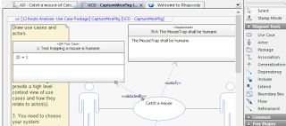
Note how external artifacts representing requirements can be placed on any diagram.


Here we can also see the OSLC links to other Jazz applications.


Jazz/am allows web browser access to the Rhapsody elements and diagrams.

To work with external test cases we need to first associate the Rhapsody Jazz/am project area with a Jazz/qm project area. I'll add an association to the Jazz/qm project area to consume Architecture Elements provided by Jazz/am.


When you close and re-open the Rhapsody project to get the Remote Artifacts Package to show the new association.


With OSLC linking, the requirements are not stored in Rhapsody, just the links. We can choose to login to access remote artifacts.


Let's add some relationships to tests in Jazz/qm. There's an Add New > OSLC Link on the diagrams right-click menu.


There's also an OSLC Links tab in the Features window.


For a Validated By link type, the picker allows me to select existing or create new test case.


The OSLC link is now shown in the OSLC Links tab.


The test case shows Validates Architecture Elements links to the Rhapsody elements.


You can use the Show in Rhapsody button to navigate to the Rhapsody client.


Jazz/qm test cases can be dragged on to diagrams similar to requirements.


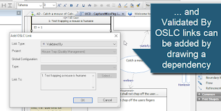
... and Validated By OSLC links can be added by drawing a dependency.


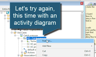
Let's try again, this time with an activity diagram.


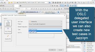
With the OSLC delegated user interface we can also create new test cases in Jazz/qm.


The rich hover in Jazz/qm allows the test engineer to view or jump to the Rhapsody element or diagram.